Designing My Self-Driving Car
22 Jun 2020
. category:
projects
.
Zero Comments
#3d-printing
#arduino
#code
#project
#python
Last Updated September 24
This year, Hack Club (A global network of code-loving high-school students) started something called Summer of Making, challenging members to learn more about tech and create cool hardware projects. I decided to use the opportunity to create something I’ve always wanted to make - a model self-driving car, inspired by the Donkey Car Project.
As of the latest update, I’ve currently developed much of the basic hardware and software and I’m mostly learning about AI and waiting for a part to arrive so I can fix my RC car and finish the build
The RC car
Originally, I had wanted to build my own RC car from scratch using aftermarket and 3d-printed parts. Eventually I actually recieved an old semi-broken RC car from a friend and decided to use it instead. However I’ll share a few of the 3dp RC car designs I found on Thigiverse here, anyway - maybe I’ll still use one of them in a future project:
- DIY RC Street Racing Car V2
- OpenRC 1:10 4WD Truggy Concept RC Car
- OpenRC F1 car - 1:10 RC Car
- OpenRC 1:10 4WD Touring RC Car
- 3D Printed RC Car V3 – Tarmo3
Fixing & modifying my RC car
For model self-driving cars, brushless motors are bad because they aren’t good for slow speeds (this is because, without brushes, there is nothing to physically slow/stabilize the armature in the motor). Self-driving cars need to be able to drive slowly for training (plus you probably don’t want your AI driving your car at super-fast speeds…). Sensored brushless motors are fine because the sensors make the motors very good at all speeds, but they are a lot more expensive than brushed motors, so I decided to replace the brushless motor in my RC car with a 27T brushed motor.
This also meant that the brushless ESC the car had would no longer work, which was perfect as I had planned to deisgn and build my own custom h-bridge with an Atmega328 microcontroller.
Finally, one of the wheel steering hubs on my car is broken, and while I’m hesitant to attempt to 3d print a replacement (it has fine threads and is a very important part that I probably couldn’t replicate with my 3d printer) replacements seem to be completely out of stock everywhere. I’ll update this post when I find a solution.
The ESC/IO board
RC cars use what’s called an ESC, or Electronic Speed Controller, to control the speed of the motor with input from the radio reciever. For brushless motors, ESCs are slightly more complicated, but for brushed motors the ESC’s job can be as simple as taking the PWM input from the reciever and mapping it to PWM output to the motor. For example, with a PWM cycle of 50% ON from the reciever might mean that the motor is supposed to be off - so the ESC outputs nothing to the motor.
However, because my ESC will primarily be controlled by a serial signal from the Rasperry Pi, I don’t need to worry about the servo input signal.
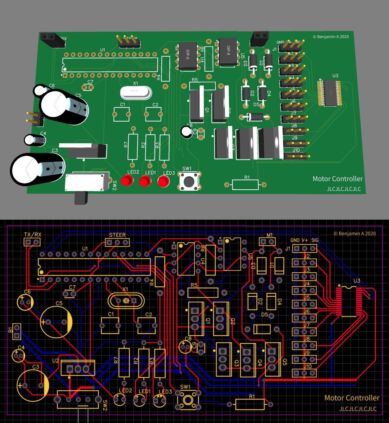
My ESC board uses an Atmega328, the most common and popular Arduino chip, in combination with an H-bridge, voltage regulator, and servo driver, which will allow for motor and steering control of the car plus room for expansion in the future. I’ve implemented and tested this on a breadboard (excluding the servo driver IC, which is surface mount; and I’m not looking forward to soldering it on the final product ![]() ).
).
I designed the first draft of my IO board schematic and PCB in EasyEDA, which is a super-easy online schematic and PCB design app:


And assembled the H-bridge and Atmega portion on a breadboard:

As you can see, the Atmega (the large chip on the right) is connected to a Raspberry pi by a few wires which I used for programming the Atmega
Programming the Atmega328p through SPI from the Raspberry pi
It turns out it’s super easy to program an Atmega from a Raspberry pi using an SPI connection with just 4 wires between the Raspberry Pi’s GPIO pins and the Atmega’s pins. I’m excited about this as it means I’m able to easily update my IO board’s firmware only by changing a few connections to the raspberry pi, eliminating the need to remove the Atmega and plug it into a programmer or anything like that.
Alexander B. made a great video tutorial about this, and if you’re interested in trying it I also explain it briefly here.
Next parts coming soon!
The latest schematic and PCB can be found here.